A Servo is a small device that has an output shaft, which can be positioned to specific angular positions. It looks like this (SG90 Mino Servo link)

The female wires are connected to three pins:
- Orange: PWM (Pulse Width Modulation)
- Red: VCC (+)
- Brown: Ground (-)
We can use three female to male wires connect those to Raspberry Pi’s GPIO pins in the following order:
- PWM –> Pin 37 (GPIO26). See the GPIO layout for details. It is the second lowest pin in the first column. It is a general purpose pin.
- VCC –> Pin 02. This is the DC Power pin with 5V. This little Servo takes 4.8~5V voltage as input. (Check your servo’s manual first before connecting!)
- Ground –> Pin 06.
Ok, that’s it for the wiring up.
Next, before we move on to control the servo, let’s spend a bit time learning what is PWM. It is a technique used to control the amount of power. As shown below, it sends a square wave, a signal switched between On and Off. The length of On and Off encodes the information you want to send.
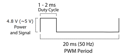
This may sound intimidating, let’s make it simply by our servo example. Our Rapberry Pi can send such square wave signal at frequency 50Hz (20ms per signal). The On part takes about 1~2ms in every cycle, while the rest is the Off part. At the same time, the little servo is listening through the PWM pin. Whenever it hears the frequency of On is at certain pre-specified value, it will rotate its shaft to certain angle. For my little servo, it can set its shaft to 0~180 degree by changing the On frequency between 1~2ms (at least that’s how manual says).
Ok, now let’s start diving into the coding part.
First, import RPi.GPIO, which is a package specifically for Rapberry Pi. GPIO.setmode specifies the numbering convention. I am using the board pin number directly.
import RPi.GPIO as GPIO
import time
GPIO.setmode(GPIO.BOARD)

sensor = 37 # choose pin 37 for PWM
GPIO.setup(sensor, GPIO.OUT)
Next, set this sensor as a PWM controller, and initialize it with 2% (i.e., 2% of cycle, which is 0.4ms per cycle). After let it run for 2 seconds, change the frequency to 4%. Remember to cleanup before exiting, so it will free up the pin.
pwm = GPIO.PWM(sensor, 50)  #PWM operates at 50 hz
pwm.start(2.0)              #start from 0 hz of "On"
time.sleep(2)
pwm.ChangeDutyCycle(4.0)
time.sleep(2)
pwm.stop()
GPIO.cleanup()
Because we are controlling the system level devices, we need to obtain sudo access, so type sudo before running python.
Remember these inexpensive servos may not have high precision. So better calibrate them before using. I scanned over a wide spectrum of frequencies and found the 0-180 degrees are mapped to 0.4-2.4ms per cycle. Hence, a linear function is suffice:
def turn(angle):
    duty = float(angle) / 18.0 + 2.0
    pwm.ChangeDutyCycle(duty)
    print "pwm set to %s for angle %s" % (duty, angle)
Hope now the Servo is working for you.
If you are still hunger to hacking the servo, try this to make it continuously rotating.
Enjoy!

Leave a comment